Table of Contents
Getting drone data into your engineering software
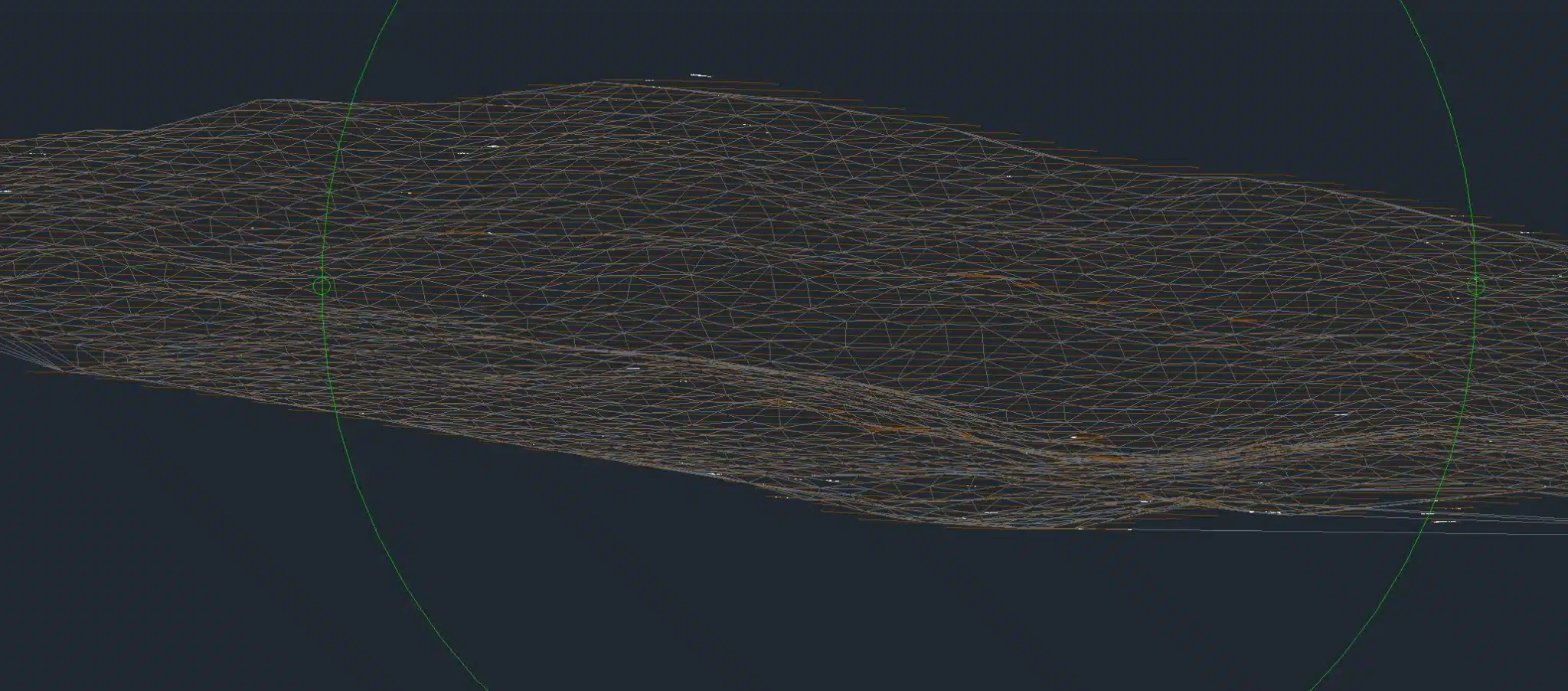
We get asked this a lot: “What format do you deliver in?” The real answer depends on whether your team runs AutoCAD Civil 3D, Trimble Business Center (TBC), or something else entirely. Both platforms handle drone survey data well, but the import path is different for each.
At Drone Services Ireland, we format everything for direct import. No messing around with coordinate conversions or file format headaches on your end.
What we deliver for Civil 3D
Civil 3D handles several drone output types natively. Here’s what most Irish engineering projects ask for:
Point cloud data (.LAS / .RCP)
Dense point cloud datasets from photogrammetry or LiDAR import directly as .LAS files, or you can convert them to Autodesk’s .RCP format through ReCap. This gives you a 3D reality model of the site that you can overlay with your design, run clash detection against, or pull volumetric analysis from.
Digital terrain models (.XML / .DWG)
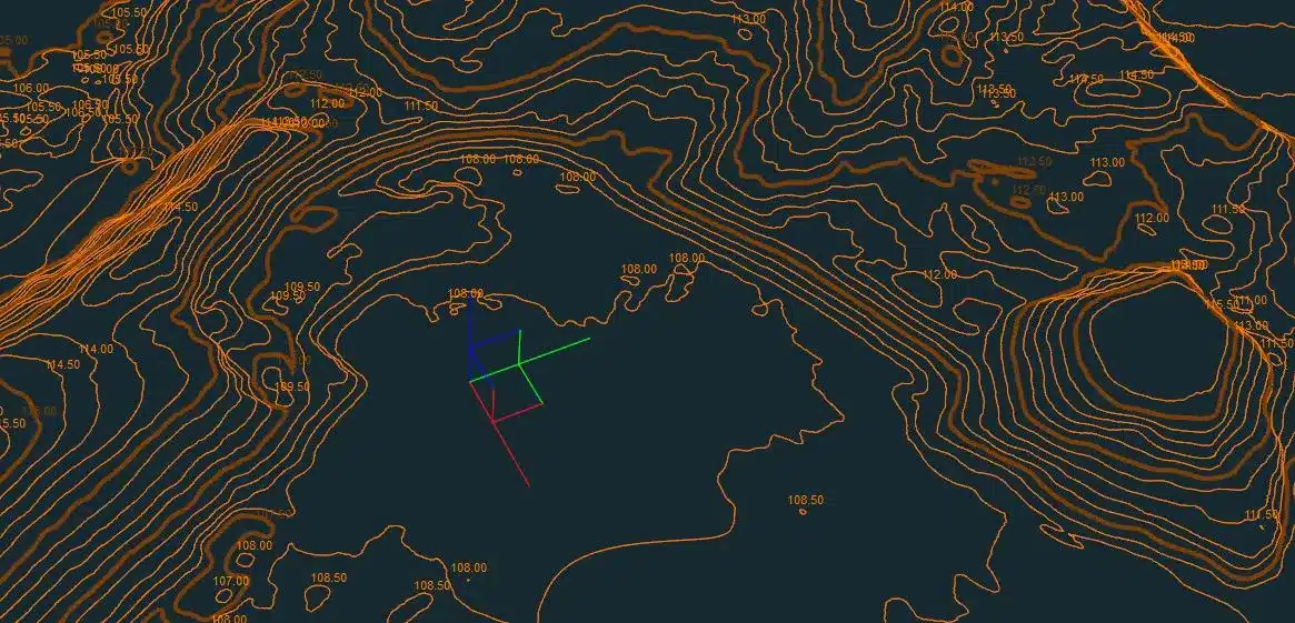
We generate TIN surfaces from classified ground points that drop straight into Civil 3D as surfaces. Engineers use these for earthworks design, grading, and cut-and-fill analysis. We process everything in Irish Transverse Mercator (ITM) so it lines up with OS mapping and any existing site survey data you already have.
Orthomosaic imagery (.TIFF / .ECW)
Georeferenced orthophotos come as GeoTIFF files that Civil 3D reads as image references. At 1.5 to 3 cm/pixel, these are far more current and detailed than anything you’ll get from OSi mapping or Google Earth. Useful for plan production and just generally understanding what’s on the ground right now.
Working with Trimble Business Center
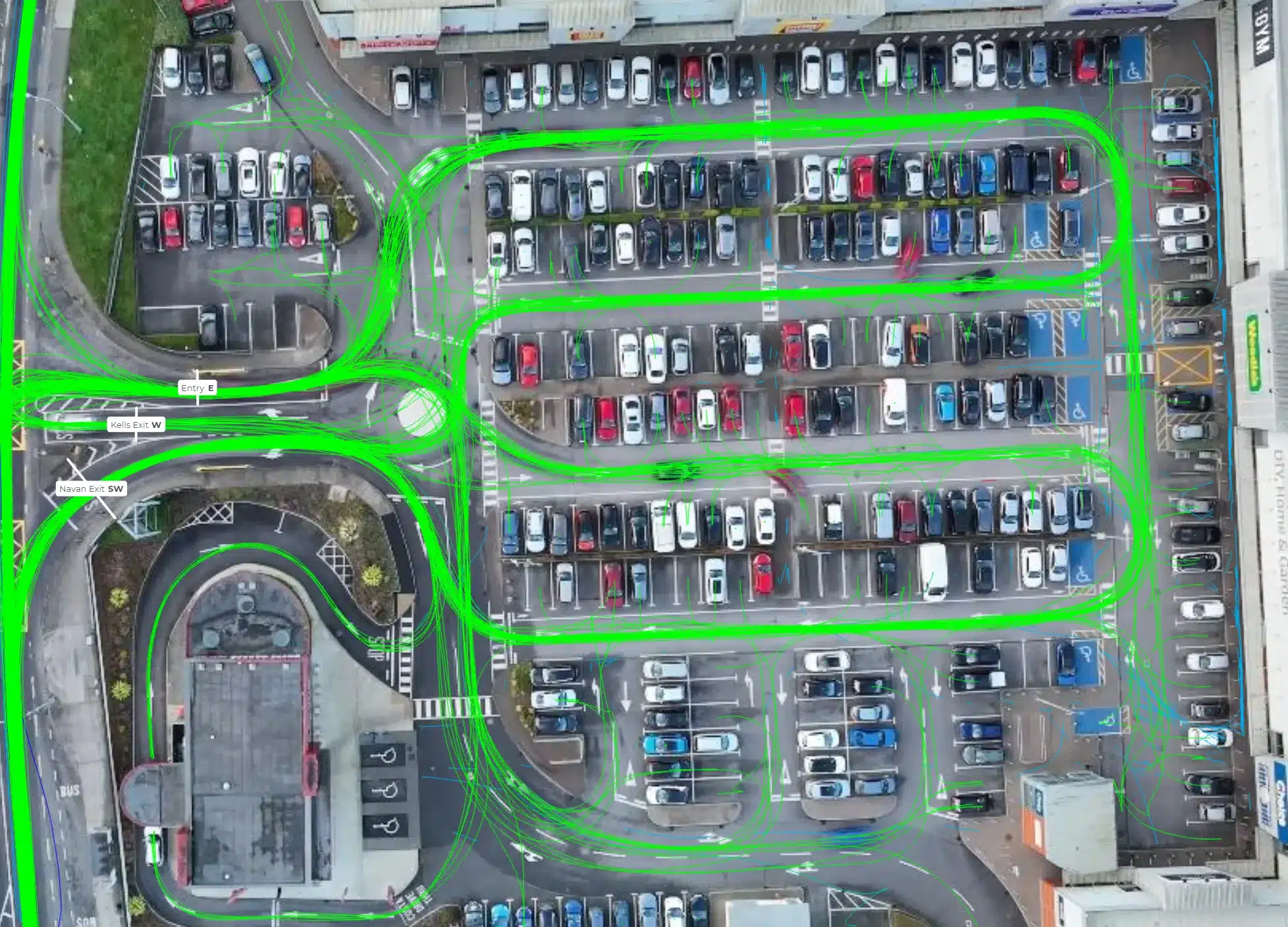
TBC has become popular with Irish surveying and engineering firms because it handles traditional GNSS and total station data alongside drone datasets in the same project. That’s a genuine advantage when you’re combining ground survey with aerial data.
Photogrammetry processing in TBC
TBC has a built-in photogrammetry module that can process drone imagery directly. We can supply raw geotagged images along with GCP coordinates if your team prefers to process in-house. Most clients prefer we deliver processed outputs ready to go, but the option’s there.
Surface and feature extraction
Where TBC really earns its keep is extracting linework from point clouds: kerb lines, road edges, ditch inverts, building footprints. When we deliver classified point clouds in .LAS format with ground, vegetation, and building classes already separated, the feature extraction in TBC is much faster than working with unclassified data.
Coordinate reference systems for Irish projects
This is where things go wrong if you’re not careful. We process everything in Irish Transverse Mercator (ITM / IRENET95) by default. For cross-border work into Northern Ireland, we can also deliver in Irish Grid or OSGB36.
If you need Malin Head or Poolbeg datum heights, we apply the OSGM15 geoid model during processing to convert from ellipsoidal to orthometric heights. The result ties into existing ground survey benchmarks and OS mapping without any fiddling on your end.
We’ve seen projects go sideways when a drone operator delivers data in WGS84 (the GPS default) and nobody catches it until the design doesn’t line up with existing ground survey. It’s a common mistake with operators who don’t work regularly with engineering clients. Every dataset we deliver comes with a coordinate reference report confirming the CRS, geoid model, and the RMSE figures from our ground control check.
For projects that involve integration with existing survey data from a land surveyor, we can work from their control network rather than establishing our own. This means the drone data and ground survey data share the same reference frame from the start – no transformation errors, no drift between datasets.
How a typical project works
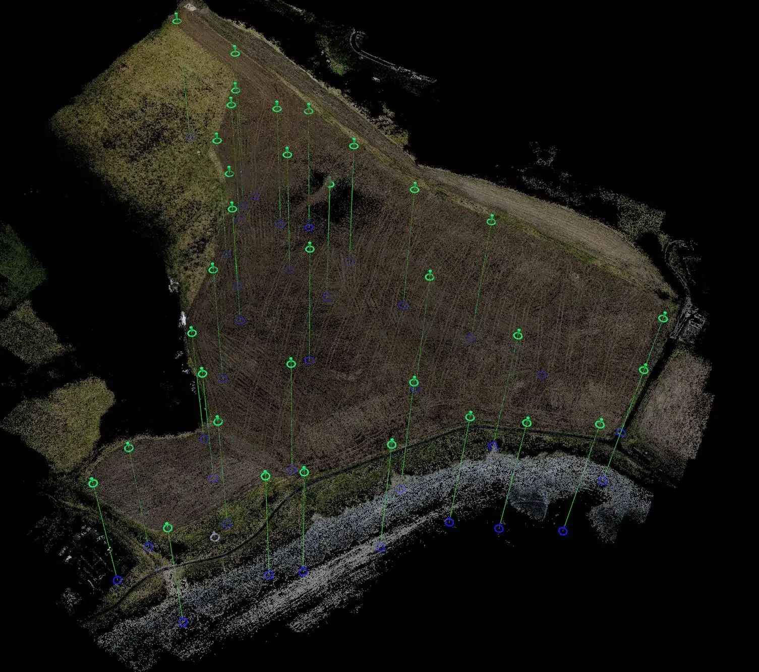
From first contact to data in your software, here’s the usual sequence:
- Pre-flight: We place and survey GCPs using GNSS in ITM coordinates, then design the flight plan for the required ground resolution
- Data capture: RTK or PPK drone survey flown at the right altitude and overlap settings
- Processing: Photogrammetric or LiDAR processing with GCP integration and accuracy checks
- QA: Independent check points verified against the delivered surface. We report RMSE values so you can see exactly what accuracy was achieved
- Delivery: Point cloud (.LAS), DTM surface (.XML/.DWG), orthomosaic (.TIFF), plus a survey report
- Your end: Import directly into Civil 3D or TBC. The data is ready to work with
What accuracy to expect
For a standard drone topographical survey with GCPs, these are the numbers we consistently hit:
- Horizontal: plus or minus 2 to 3 cm RMSE (photogrammetry with GCPs)
- Vertical: plus or minus 3 to 5 cm RMSE on hard surfaces, 5 to 8 cm on vegetated ground
- LiDAR: plus or minus 2 to 3 cm vertical on bare earth, with the bonus of vegetation penetration
These numbers aren’t theoretical – they’re verified on every project. We place independent check points that aren’t used in the processing, then measure the difference between our delivered surface and those known positions. The RMSE values we report come from that independent check, not from the processing software’s internal statistics (which are typically optimistic).
If your project needs tighter tolerances on specific areas – say, around an existing structure or a tie-in to a live road – we can increase the GCP density in those zones. We’ve hit sub-2cm accuracy on hard surfaces where the GCP spacing was under 50m.
That’s more than adequate for detailed design, earthworks calculations, and planning submissions on the vast majority of Irish civil engineering projects. We’ve written more about this in our guide on drone survey accuracy.
Talk to us about your project
If you need drone survey data that drops straight into your Civil 3D or TBC workflow, get in touch with your requirements. We’ll confirm formats, coordinate system, and accuracy spec before we fly. You can also browse our surveying services or read about our survey equipment.